Microcontroller
A microcontroller (sometimes abbreviated µC, uC or MCU) is a small computer on a single integrated circuit containing a processor core, memory, and programmable input/output peripherals. Program memory in the form of NOR flash or OTP ROM is also often included on chip, as well as a typically small amount of RAM. Microcontrollers are designed for embedded applications, in contrast to themicroprocessors used in personal computers or other general purpose applications.
Interfacing
A microcontroller can be considered a self-contained system with a processor, memory and peripherals and can be used as an embedded system.[8] The majority of microcontrollers in use today are embedded in other machinery, such as automobiles, telephones, appliances, and peripherals for computer systems.
While some embedded systems are very sophisticated, many have minimal requirements for memory and program length, with no operating system, and low software complexity. Typical input and output devices include switches, relays, solenoids, LEDs, small or custom LCD displays, radio frequency devices, and sensors for data such as temperature, humidity, light level etc. Embedded systems usually have no keyboard, screen, disks, printers, or other recognizable I/O devices of a personal computer, and may lack human interaction devices of any kind.
Interrupts[edit]
Micro controllers must provide real time (predictable, though not necessarily fast) response to events in the embedded system they are controlling. When certain events occur, an interrupt system can signal the processor to suspend processing the current instruction sequence and to begin an interrupt service routine (ISR, or "interrupt handler"). The ISR will perform any processing required based on the source of the interrupt, before returning to the original instruction sequence. Possible interrupt sources are device dependent, and often include events such as an internal timer overflow, completing an analog to digital conversion, a logic level change on an input such as from a button being pressed, and data received on a communication link. Where power consumption is important as in battery operated devices, interrupts may also wake a microcontroller from a low power sleep state where the processor is halted until required to do something by a peripheral event.
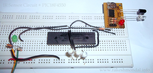
The
output from the IR sensor circuit will be connected to pins of a
PIC18f4550 microcontroller and the microcontroller will regard it as
digital input to read either 1 or 0. According to the output from the
IR sensor module, the PIC18F4550 will respond by glowing led. Since we
just want to read some voltage in the microcontroller as input (either
High or low) hence we are going to configure input pins as digital to
read just 1 or 0 from the sensor. - See more at:
http://www.rakeshmondal.info/IR-Sensor-Interface-pic18f4550-input#sthash.gt45TPe7.dpufThe
output from the IR sensor circuit will be connected to pins of a
PIC18f4550 microcontroller and the microcontroller will regard it as
digital input to read either 1 or 0. According to the output from the
IR sensor module, the PIC18F4550 will respond by glowing led. Since we
just want to read some voltage in the microcontroller as input (either
High or low) hence we are going to configure input pins as digital to
read just 1 or 0 from the sensor. - See more at:
http://www.rakeshmondal.info/IR-Sensor-Interface-pic18f4550-input#sthash.gt45TPe7.dpuf
The
output from the IR sensor circuit will be connected to pins of a
PIC18f4550 microcontroller and the microcontroller will regard it as
digital input to read either 1 or 0. According to the output from the
IR sensor module, the PIC18F4550 will respond by glowing led. Since we
just want to read some voltage in the microcontroller as input (either
High or low) hence we are going to configure input pins as digital to
read just 1 or 0 from the sensor. - See more at:
http://www.rakeshmondal.info/IR-Sensor-Interface-pic18f4550-input#sthash.gt45TPe7.dpuf
The
output from the IR sensor circuit is connected to RA0 of the pic18f4550
which is configured as input with TRISB registers, and the output will
be displayed on LED connected across RD7, RD6,RD5 (PORTD) and RB0 and
RB1 (PORTB) which are configured as output pins. Follow the schematic
below.
Schematic (IR sensor and PIC18F4550 microcontroller)
In this project we don’t need to perform any Analog to Digital
Conversion(ADC), hence we are going to turn the ADC off (ADCON0bits.ADON
= 0) and configure all the PINS to Digital. At the default 1 MHZ
oscillator frequency the output sometimes gives unstable result, hence
tuning the microcontroller to 8MHZ solved the problem, Please note that
pic18f4550 works by default on 1 MHZ and you can change the OSCCON bits
settings to tune the oscillator frequency according to your requirement.
Search in pic18f4550 datasheet
for OSCCON register bits and you will find a nice description and bits
settings table for available oscillator frequency and settings to
configure the microcontroller oscillator frequency. Here I have
configured the internal oscillator to 8MHZ to avoid switch debouncing.
However it works well with 1MHZ settings as well. As a better plan the
comparator is also turned off to avoid any conflict.
All
the resistors in the above Schematic is 1k resistance. If possible, it
is also recommended to add a IC 7805 liner Voltage regulator IC
as a source of +5V to avoid any voltage fluctuation which could
possibly damage the microcontroller. Make sure the input voltage to
pic18f4550 must never exceed +5v. Please do read the excellent
pic18f4550 datasheet provided by microchip.

Source Code:
MPLAB IDE and C18 Compiler is used for
compiling the source code, however MPLAB X IDE and XC8 Compiler can be
also used with no difficulty. Download the entire project at the end of
the source code below with compiled firmware.
SOURCE CODE :infraredinput.c
/*
* File: infraredinput.c
* Author: ron
* December 10, 2012, 1:21 PM
*/
#include <p18f4550.h> // Include Header for PIC18F4550
#define switch1 PORTAbits.RA0 // Switch on RA0
#define led1 LATDbits.LATD7 // led1
#define led2 LATDbits.LATD6 // led2
#define led3 LATBbits.LATB0 // led3
#define led4 LATBbits.LATB1 // led4
#define led5 LATBbits.LATB2 // led5
void main (void)
{
/* If you want your microcontroller to work at 1MHZ then comment the three lines below */
OSCCONbits.IRCF0 = 1 ; // set internal clock to 8 MHz
OSCCONbits.IRCF1 = 1; // For Avoiding switch debouncing problem
OSCCONbits.IRCF2= 1; //
/* Input output settings*/
TRISAbits.TRISA0 = 1; // RA0 Input for taking input from IR sensor
TRISDbits.TRISD7 = 0; // Port D pins output
TRISDbits.TRISD6 = 0;
TRISBbits.TRISB0 = 0; // Port B pins Output
TRISBbits.TRISB1 = 0;
TRISBbits.TRISB2 = 0;
CMCON = 0x07; // Disable Comparator
ADCON1bits.PCFG0 = 1; // These 4 settings below determines the analog or digital input
ADCON1bits.PCFG1 = 1; // In our case we are making all the pins digital
ADCON1bits.PCFG2 = 1; // by setting them as 1111
ADCON1bits.PCFG3 = 1; // Check with the datasheet for a nice desc of these bits and config.
ADCON0bits.ADON = 0; // Disabled ADC
while(1)
{ //Forever Loop
if(switch1 == 1) // On reading IR sensor value ON
{ //Turn led ON
led1 = 1;
led2 = 1;
led3 = 1;
led4 = 1;
led5 = 1; }
else if ( switch1 == 0) // On reading IR Sensor Value OFF
{ //Turn led off
led1 = 0;
led2 = 0;
led3 = 0;
led4 = 0;
led5 = 0; }
else { }
} //End While loop --forever
}
/* THE END */
The coding above is pretty much self-explanatory, and comment lines must be also helpful for better understanding.
- See more at: http://www.rakeshmondal.info/IR-Sensor-Interface-pic18f4550-input#sthash.gt45TPe7.dpuf
The
output from the IR sensor circuit is connected to RA0 of the pic18f4550
which is configured as input with TRISB registers, and the output will
be displayed on LED connected across RD7, RD6,RD5 (PORTD) and RB0 and
RB1 (PORTB) which are configured as output pins. Follow the schematic
below.
Schematic (IR sensor and PIC18F4550 microcontroller)
In this project we don’t need to perform any Analog to Digital
Conversion(ADC), hence we are going to turn the ADC off (ADCON0bits.ADON
= 0) and configure all the PINS to Digital. At the default 1 MHZ
oscillator frequency the output sometimes gives unstable result, hence
tuning the microcontroller to 8MHZ solved the problem, Please note that
pic18f4550 works by default on 1 MHZ and you can change the OSCCON bits
settings to tune the oscillator frequency according to your requirement.
Search in pic18f4550 datasheet
for OSCCON register bits and you will find a nice description and bits
settings table for available oscillator frequency and settings to
configure the microcontroller oscillator frequency. Here I have
configured the internal oscillator to 8MHZ to avoid switch debouncing.
However it works well with 1MHZ settings as well. As a better plan the
comparator is also turned off to avoid any conflict.
All
the resistors in the above Schematic is 1k resistance. If possible, it
is also recommended to add a IC 7805 liner Voltage regulator IC
as a source of +5V to avoid any voltage fluctuation which could
possibly damage the microcontroller. Make sure the input voltage to
pic18f4550 must never exceed +5v. Please do read the excellent
pic18f4550 datasheet provided by microchip.
Source Code:
MPLAB IDE and C18 Compiler is used for
compiling the source code, however MPLAB X IDE and XC8 Compiler can be
also used with no difficulty. Download the entire project at the end of
the source code below with compiled firmware.
SOURCE CODE :infraredinput.c
/*
* File: infraredinput.c
* Author: ron
* December 10, 2012, 1:21 PM
*/
#include <p18f4550.h> // Include Header for PIC18F4550
#define switch1 PORTAbits.RA0 // Switch on RA0
#define led1 LATDbits.LATD7 // led1
#define led2 LATDbits.LATD6 // led2
#define led3 LATBbits.LATB0 // led3
#define led4 LATBbits.LATB1 // led4
#define led5 LATBbits.LATB2 // led5
void main (void)
{
/* If you want your microcontroller to work at 1MHZ then comment the three lines below */
OSCCONbits.IRCF0 = 1 ; // set internal clock to 8 MHz
OSCCONbits.IRCF1 = 1; // For Avoiding switch debouncing problem
OSCCONbits.IRCF2= 1; //
/* Input output settings*/
TRISAbits.TRISA0 = 1; // RA0 Input for taking input from IR sensor
TRISDbits.TRISD7 = 0; // Port D pins output
TRISDbits.TRISD6 = 0;
TRISBbits.TRISB0 = 0; // Port B pins Output
TRISBbits.TRISB1 = 0;
TRISBbits.TRISB2 = 0;
CMCON = 0x07; // Disable Comparator
ADCON1bits.PCFG0 = 1; // These 4 settings below determines the analog or digital input
ADCON1bits.PCFG1 = 1; // In our case we are making all the pins digital
ADCON1bits.PCFG2 = 1; // by setting them as 1111
ADCON1bits.PCFG3 = 1; // Check with the datasheet for a nice desc of these bits and config.
ADCON0bits.ADON = 0; // Disabled ADC
while(1)
{ //Forever Loop
if(switch1 == 1) // On reading IR sensor value ON
{ //Turn led ON
led1 = 1;
led2 = 1;
led3 = 1;
led4 = 1;
led5 = 1; }
else if ( switch1 == 0) // On reading IR Sensor Value OFF
{ //Turn led off
led1 = 0;
led2 = 0;
led3 = 0;
led4 = 0;
led5 = 0; }
else { }
} //End While loop --forever
}
/* THE END */
* File: infraredinput.c
* Author: ron
* December 10, 2012, 1:21 PM
*/
#include <p18f4550.h> // Include Header for PIC18F4550
#define switch1 PORTAbits.RA0 // Switch on RA0
#define led1 LATDbits.LATD7 // led1
#define led2 LATDbits.LATD6 // led2
#define led3 LATBbits.LATB0 // led3
#define led4 LATBbits.LATB1 // led4
#define led5 LATBbits.LATB2 // led5
void main (void)
{
/* If you want your microcontroller to work at 1MHZ then comment the three lines below */
OSCCONbits.IRCF0 = 1 ; // set internal clock to 8 MHz
OSCCONbits.IRCF1 = 1; // For Avoiding switch debouncing problem
OSCCONbits.IRCF2= 1; //
/* Input output settings*/
TRISAbits.TRISA0 = 1; // RA0 Input for taking input from IR sensor
TRISDbits.TRISD7 = 0; // Port D pins output
TRISDbits.TRISD6 = 0;
TRISBbits.TRISB0 = 0; // Port B pins Output
TRISBbits.TRISB1 = 0;
TRISBbits.TRISB2 = 0;
CMCON = 0x07; // Disable Comparator
ADCON1bits.PCFG0 = 1; // These 4 settings below determines the analog or digital input
ADCON1bits.PCFG1 = 1; // In our case we are making all the pins digital
ADCON1bits.PCFG2 = 1; // by setting them as 1111
ADCON1bits.PCFG3 = 1; // Check with the datasheet for a nice desc of these bits and config.
ADCON0bits.ADON = 0; // Disabled ADC
while(1)
{ //Forever Loop
if(switch1 == 1) // On reading IR sensor value ON
{ //Turn led ON
led1 = 1;
led2 = 1;
led3 = 1;
led4 = 1;
led5 = 1; }
else if ( switch1 == 0) // On reading IR Sensor Value OFF
{ //Turn led off
led1 = 0;
led2 = 0;
led3 = 0;
led4 = 0;
led5 = 0; }
else { }
} //End While loop --forever
}
/* THE END */
The coding above is pretty much self-explanatory, and comment lines must be also helpful for better understanding.
- See more at: http://www.rakeshmondal.info/IR-Sensor-Interface-pic18f4550-input#sthash.gt45TPe7.dpuf
No comments:
Post a Comment